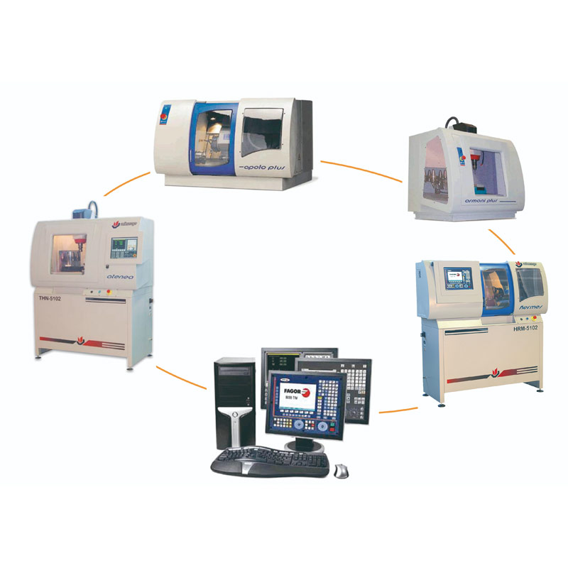
Wincontrol Software
Main characteristics
- Assisted creation of new projects.
- Editing with graphic help menu for programming all ISO functions.
- Editing using the Copy-cut-Paste functions of Windows.
- Customisation of the characteristics of the machine which is going to be used.
- Simulation of different tool geometries for lathe and milling machine.
- Simulation in various 3D views with representation of the tool and paths.
- Representation of the jaw and the chuck.
- Selection of different colours for the different tools.
- Calculation of machining time.
- Collision detection of the tool and the handle with the part and the jaw chuck.
- Preparation of the machine for executing the machining. Control of axes, speeds, tool setting, pre-selection of sources.
- Control of machining of the part in the machine, with continuous execution or block by block.
- Printing of all the data, the CNC programme and the graphic representations.
To all of these features we must also include the high quality graphics that contribute to the speedy understanding of the simulated machining and to the clear detection of errors.
DESCRIPTION
Wincontrol is distributed with the Alecop PC machines and allows the user to edit the ISO code, simulate the execution of programmes and control machines by using the control simulator of their choice:
- FAGOR
- SINUMERIK
- FANUC
FEATURES
Work process
WinControl allows the user to learn the processes necessary to define the machining of a work-piece through practical exercises of this, starting from the plan and the manufacturing process and finishing with the control and execution in the machine.
Choose numerical control

Choose the type of control simulator with which we are going to work. Hereinafter, the code editing and the screen display of the control are those chosen by the user.
Elaboration of the CNC programme (with the programming help menu)

Use of the help menu to choose the appropriate code and define it parameters.
Detection of syntactical errors while writing or via the Analyse option to verify the complete programme.
Definition of the data of the machine, part, tools and origin of work-piece

Definition of the machine data to determine the possibility of machining the part on the machine.
Representation of the jaws and the chuck to detect tool collisions.
Definition of the tool with its geometry and corrector
Machining simulation

Different graphical representations of the part (zoom, number of views, sections, angle, etc.) and the type of simulation (solid, trajectory with or without compensation).
Detection of programming, syntactical and trajectory errors.
Machining on the machine by handling of the chosen control panel
Execution of the machining of the part on the machine with stoppage control, block by block execution, MDI programming, speed control, device control, etc.
The machine handling is carried out through the simulation of the control panel or with a generic representation.


