DESCRIPTION
Technical Description
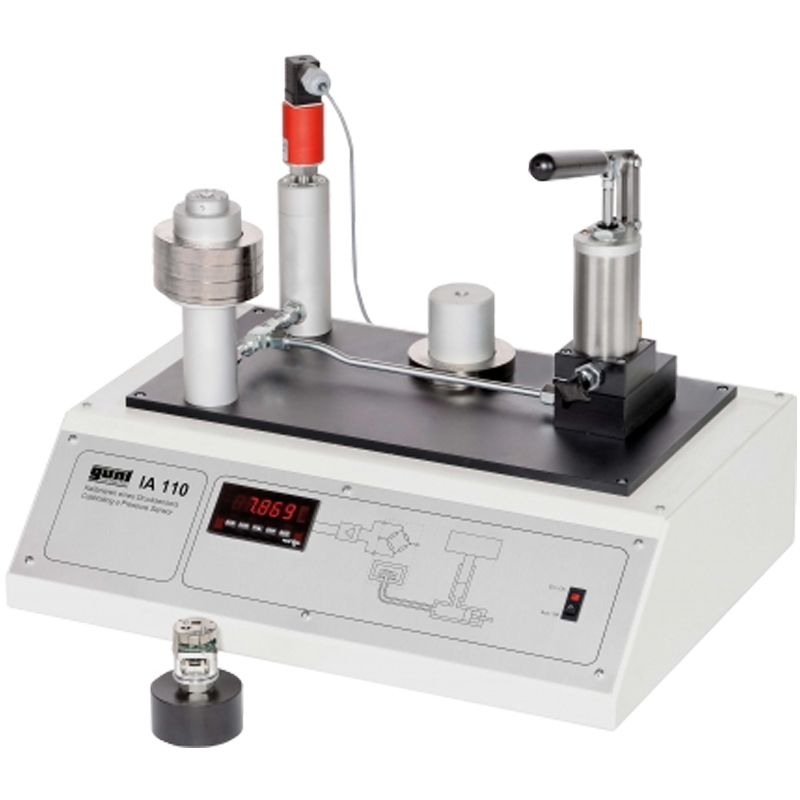
The experimental unit IA 110 can be used to calibrate an electronic pressure sensor under practical conditions.
The test pressure is generated with a conventional piston manometer. The piston is loaded with weight rings and generates a defined test pressure p = Fw/AP, where Fwis the force due to the weights and AP is the cross-sectional area of the piston. A hand-operated spindle is used to relieve the pressure after measurement allowing the piston to return to a rest position. The influence of friction is minimised by rotating the piston during measurement. The test pressure generated in this way is applied to the diaphragm of a pressure sensor. The pressure-dependent electrical output signal is indicated on a digital display.
The pressure sensor used is a state-of-the-art ceramic measuring cell, in which strain-dependent piezo resistors are mounted on a ceramic diaphragm. The resistors are configured to form a measuring bridge. An integrated amplifier circuit evaluates the pressure-dependent detuning of the measuring bridge and outputs a proportional voltage signal.
The kit also includes a second pressure sensor in the form of a cutaway model for enhanced clarity. The entire experimental unit is contained in a compact housing, and is easy to handle.
The well-structured instructional material sets out the fundamentals and provides a step-by-step guide through the experiments.
 Learning Objectives / Experiments
- familiarisation with, and carrying out of the calibration of an electronic pressure sensor
- plotting the sensor output signal dependent on the pressure applied
- familiarisation with the design and operation of a piezo-resistive electronic pressure sensor
- familiarisation with the installation and connection of the pressure sensor
- information on applications, measuring ranges and accuracies of typical electronic pressure sensors
FEATURES
Specification
[1] calibration unit with dead-weight piston manometer and hand-operated spindle
[2] electronic pressure sensor with ceramic measuring cell, integrated amplifier and voltage output
[3] digital display for output signal
[4] additional pressure sensor as cutaway model
[5] set of weights
[6] transmission medium: hydraulic oil
[7] process schematic on front panel
Technical Data
Pressure sensor
- measuring range: 0...2,5bar
- supply: 24VDC
- output signal: 0...10VDC
Piston manometer with pressure piston
- diameter: 12mm
- number of weights: 5
- pressure graduations: 0,5 - 1,0 - 1,5 - 2,0 - 2,5bar
Digital display: 4 1/2 digits
Hydraulic oil: HLP ISO 32
Dimensions and Weight
LxWxH: 600x450x450mm
Weight: approx. 20kg Required for Operation
230V, 50/60Hz, 1 phase or 120V, 60Hz/CSA, 1 phase
Scope of Delivery
1 experimental unit
1 set of weights
1L hydraulic oil
1 cutaway model of pressure sensor
1 set of instructional material


